IR Remote Control
Standard version
This is the first circuit I created. Working principles are described in the "Basic Info" page. The transistor connected to the led isn't really necessary, but I prefer using it to get maximum power. The Pushbutton SW1 is placed between the battery and the ground, so that it is possible to use a transistor in open-collector configuration to turn on the remote control.
It's just like the original Nikon ML-L3 remote control (slightly bigger, but I have already explained why I haven't used SMD components)
Building this circuit is simple. You can use a homemade PCB (Printed Circuit Board), a matrix development board or fix most of the components directly onto the microcontroller (see the "feedback" section). In half an hour you can be ready to take the first shot.
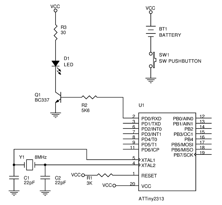
Schematic diagram
To download schematic, PCB layout, source code and compiled program, go to the download section
Photogallery
My very first photo. I was testing the circuit mounted on a solderless breadboard, and to my surprise... it worked! So I have a photo of my belly! Not an interesting photo, but it’s the first one...
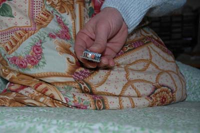
The first photo taken with the assembled remote control
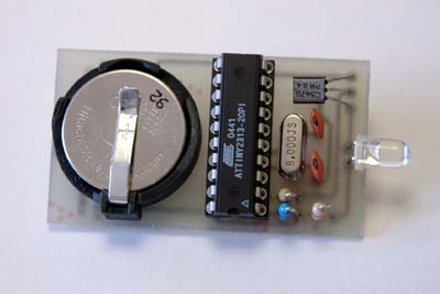
Remote control, component layer
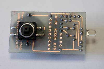
Remote control, solder layer
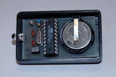
The remote control in the box
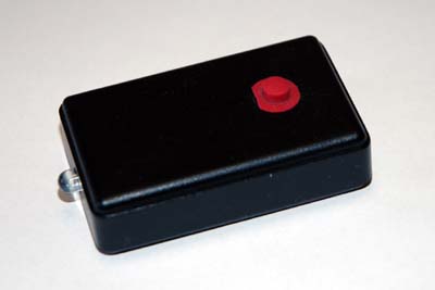
The box closed
