OML-L3
The open hardware project to build an inexpensive and customizable infrared remote control for Nikon cameras
Designed for the Nikon D70, it works with every camera supported by ML-L1 and ML-L3 such as D40, D40X, D50, D60, D70, D70s, D80, D90, D7000, D5000, D5100, D3000, Coolpix 8400, 8800, P6000, P7000, P7100, Nikon 1 J1/V1
The story
Searching for an alternative to buying an expensive remote control for my Nikon D70, I found a small program for the Palm. It works well, but the Palm isn’t really comfortable for that kind of use.
At this point I decided to build a pocket circuit, using a micro-controller, to release the camera’s shutter. The choice of which processor to use was simple: I’ve been working for many years with the ST6 family, but recently, I discovered the AVR micro-controllers. Why not use one of these? It would be a great way to learn how to create a real application with these amazing chips.
01/2012 : I started to work to this project in the far 2005, when the original ML-L3 was very expensive.
Some theory
Using an infrared demodulator and a digital oscilloscope I captured the wave generated by the Palm. Fortunately the waveform is quite simple, so hardware and software are easy to develop. The captured data was something like shown in figure 1
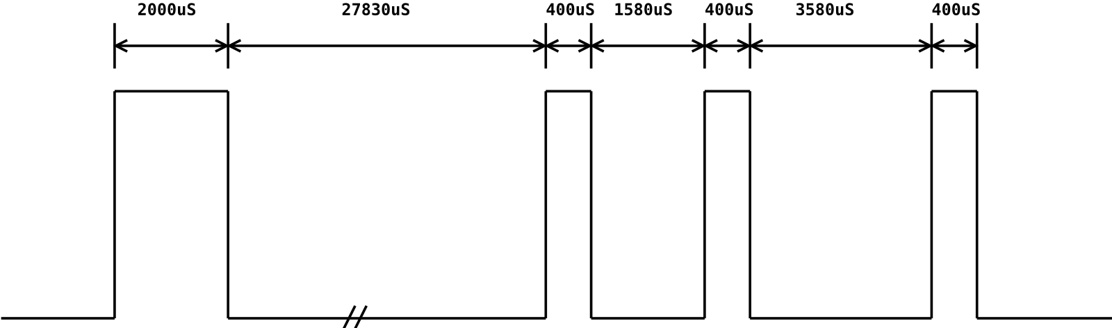 Figure 1
Note: High levels show when the transmitter’s led is on, low levels when the led is off. The same waveform is repeated a second time after about 63.2 msec. The diagram is not in scale.
Note 2: The waveform in the figure is slight different from the original captured using the Palm. In March 2006 I received from Mikey the waveform recorded directly from an original Nikon remote control. A good job, and the circuit started to work perfectly under every condition. The three short pulses reported were 390,410 and 400 usec. As reported by many readers, it's highly probable that the right timing is 400,400 and 400, so, in January 2012 I updated the timing diagram again. Both configurations work fine, so, at moment, I think there's no need to change the source code of the program.
I think that the receiver of the DSLR is built with software and not with some hardware decoder, and it should work as follows:
- Wait for a start pulse (2000 usec)
- There must be no pulse for 27830 usec (pause)
- Receive a pulse (400 usec)
- Pause (1580 usec)
- Receive a second pulse (400 usec)
- Longer pause (3580 usec)
- Receive the last pulse (400 usec)
If one step fails, reception is aborted.
Before concluding this paragraph, I must say a few words regarding the transmitter. Most infrared transmissions operate by modulating the led with a relatively high frequency (in most cases 38.4KHz or 40KHz). This means that when we have to send a bit value “1” the led is turned on and off 38400 or 40000 times in one second. When we have to send a bit “0” the led remains turned off. My Palm uses a frequency of 40KHz, but I don’t know what frequency the original Nikon ML-L3 uses. In this case however, it isn’t really a problem: everything works fine!
03/2006 : Mikey reported that the frequency is 38.4KHz.
Now that we know how the remote control works, we are ready to start the developing phase.
Hardware
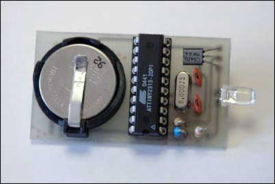
As mentioned above, I decided to use an AVR 8-bit RISC MCU. I chose the ATTiny2313 model for various reasons: low cost, easy to find, and I have it in my toolbox. If you prefer, you should be able to use every AT90, ATMega and ATTiny simply recompiling the software. An SMD version of the chip would help reduce dimensions, but I wanted to keep the circuit simple to build, so my design uses a DIP version.
To be compact a small battery must power the circuit: a lithium battery like CR2032 could be a good choice. A battery holder like the one I used is easily found on most old PC motherboards.
We will see in the next paragraph that we need a precise clock to generate a good 38,4KHz square wave, so a quartz crystal is needed as oscillator. I have a lot of 8MHz, so I selected this as clock frequency. Someone could think that this “high” frequency causes too much battery consumption, but we must remember that transmission is very short and the power absorbed by the led is much higher compared to the MCU. By the way, it’s possible to reduce the frequency carefully reading the next paragraph.
Hardware details outlined; it’s time to write down the program.
Software
First of all, we need a precise time-base reference to make the led blink at 38,4KHz. This implies that the led is powered on for 13usec (13.0208 to be precise) and then turned off for the same time. To do this, we need to know exactly the processor’s clock frequency and how many clock cycles are needed to reach the 13usec. The clock frequency is 8MHz, so every clock cycle requires 125 nanoseconds or 0,125usec. Obviously, after 104 clock cycles the requested time has been reached. Considering that the “CALL” instruction, “RET”, “SBI” (led on) and “CBI” (led off) spend cycles, we can write the following routine:
- delay130:
- ; This is a 13.0 uS delay (104 cycles @ 8MHz)
- ;
- ; sbi/cbi = 2 cycles
- ; rcall = 3 cycles
- ;
- ldi DelayReg,32 ; 1 cycle
- delay125_0:
- dec DelayReg ; 1 cycle
- brne delay125_0 ; 2 cycle if jump to label, 1 if not
- ret ; 4 cycles
03/2006 : the delay routine shown above is the original one. The version 2.0 of the program has been altered to obtain the maximum precision. The basis however, remains the same.
Now, with this routine, it’s as if we had a clock with a period of 13 microseconds: why not use this for the global waveform generation?
I can explain the idea with an example: the start pulse needs the led blinking for 2000usec or in other terms, approximately 154 * 13usec. If we count 77 times “led on for 13usec, led off for 13usec” the start pulse has been generated!
Here’s the code:
- ;(Start pulse)
- ldi R17,77 ; (13.0 uS * 2 ) * 77 = 2002 uS
- startpulse:
- sbi PORTD,0 ; Led on
- rcall delay130 ; Wait 13 uS
- cbi PORTD,0 ; Led off
- rcall delay130 ; wait 13 uS
- dec R17
- brne startpulse
03/2006 : The version 2.0 of the program has been altered to obtain the maximum precision. The basis however, remains the same.
After writing a few more loops like the one above, we’re done. Remember, the processor must send a complete “train” of pulses twice, and then stop. For battery saving, use the “SLEEP” command. For the complete, operational, source code, take a look at the download section.
Final considerations
In the title I wrote “inexpensive and customizable”. Why? Well, “inexpensive” is easy to explain: with only 10 USD (about 10 Euro), maybe even less, you can build a perfectly functional remote control for your Nikon. (This was true in the 2005)
For “customizable” imagine the following situations:
- You’re a few meters behind your camera, maybe hidden by a tree or a wall.
- Your camera is mounted on a tripod and you want to take a shot without touching the equipment. It’s uncomfortable having to stretch your arm to the front of the DSLR.
- You want to stay 50-100 meters away from the apparatus and the IR led doesn’t have such a long range (make sure no one can steal your jewel).
- You want to take a picture every 1, 2, 5 or 10 minutes automatically.
You have the hardware (with schematics), you have the software (with source code), you have a brain : use them and you will find a solution for all your needs!
If you have no ideas, here are some suggestions:
- Connect a long, flexible, electric cable from the pcb to the pushbutton switch and place the remote control somewhere in the front of the camera.
- Connect a very supple, not too long, electric cable from the pcb to the IR led. Fasten the led (maybe using the camera’s strap) to the front and take the box with the pushbutton in your hand.
- Use a radio remote control to activate the IR remote control. An NPN transistor in open-collector mode can be used to simulate the switch press.
- Build a programmable timer with relay or open-collector output. Remember that after 15 minutes of inactivity the camera deactivates the IR receiver. An even better alternative is modifying the micro’s software allowing it to send two-pulse sequences at regular intervals. The latter requires a superior-quality battery.
- You can also connect a second switch to the micro and, altering the program, send a non-stop sequence. In this way the camera operates in continuous mode until you release the button.
Special thanks
- Gerhard Schmidt (DG4FAC) – AVR tutorial
- Brian Hammill - Basic idea for 40KHz routine
- Pitronics - SP12 AVR programming software
- Mikey for original Nikon ML-L3 data
- Tamiko for English document revision
